Pipelined datapath and control
A pipeline processor can be represented in two dimensions, as shown in Figure 5.1. Here, the pipeline segments (Seg #1 through Seg #3) are arranged vertically, so the data can flow from the input at the top left downward to the output of the pipeline (after Segment 3). The progress of an instruction is charted in blue typeface, and the next instruction is shown in red typeface.
There are three things that one must observe about the pipeline. First, the work (in a computer, the ISA) is divided up into pieces that more or less fit into the segments alloted for them. Second, this implies that in order for the pipeline to work efficiently and smoothly, the work partitions must each take about the same time to complete. Otherwise, the longest partition requiring time T would hold up the pipeline, and every segment would have to take time T to complete its work. For fast segments, this would mean much idle time. Third, in order for the pipeline to work smoothly, there must be few (if any) exceptions or hazards that cause errors or delays within the pipeline. Otherwise, the instruction will have to be reloaded and the pipeline restarted with the same instruction that causes the exception. There are additional problems we need to discuss about pipeline processors, which we will consider shortly.
It is easily verified, through inspection of Figure 5.1., that the response time for any instruction that takes three segments must be three times the response time for any segment, provided that the pipeline was full when the instruction was loaded into the pipeline. As we shall see later in this section, if an N-segment pipeline is empty before an instruction starts, then N + (N-1) cycles or segments of the pipeline are required to execute the instruction, because it takes N cycles to fill the pipe.
Note that we just used the term “cycle” and “segment” synonomously. In the type of pipelines that we will study in this course (which includes the vast majority of pipeline processors), each segment takes one cycle to complete its work. Thus, an N-segment pipeline takes a minimum time of N cycles to execute one instruction. This brings to mind the performance issues discussed in Section 5.1.1.5.
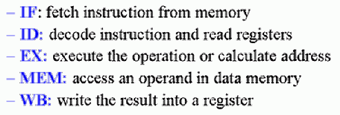
Work Partitioning. In the previous section, we designed a multicycle datapath based on the assumption that computational work associated with the execution of an instruction could be partitioned into a five-step process, as follows:
Performance. Because there are N segments active in the pipeline at any one time (when it is full), it is thus possible to execute N segments concurrently in any cycle of the pipeline. In contrast, a purely sequential implementation of the fetch-decode-execute cycle would require N cycles for the longest instruction. Thus, it can be said that we have O(N) speedup. As we shall see when we analyze pipeline performance, an exact N-fold speedup does not always occur in practice. However it is sufficient to say that the speedup is of order N.
Pipeline Datapath Design and Implementation
As shown in Section 5.1.2.4, the work involved in an instruction can be partitioned into steps labelled IF (Instruction Fetch), ID (Instruction Decode and data fetch), EX (ALU operations or R-format execution), MEM (Memory operations), and WB (Write-Back to register file). We next discuss how this sequence of steps can be implemented in terms of MIPS instructions.
MIPS Instructions and Pipelining
In order to implement MIPS instructions effectively on a pipeline processor, we must ensure that the instructions are the same length (simplicity favors regularity) for easy IF and ID, similar to the multicycle datapath. We also need to have few but consistent instruction formats, to avoid deciphering variable formats during IF and ID, which would prohibitively increase pipeline segment complexity for those tasks. Thus, the register indices should be in the same place in each instruction. In practice, this means that the rd, rs, and rt fields of the MIPS instruction must not change location across all MIPS pipeline instructions.
Additionally, we want to have instruction decoding and reading of the register contents occur at the same time, which is supported by the datapath architecture that we have designed thus far. Observe that we have memory address computation in the lw and sw instructions only, and that these are the only instructions in our five-instruction MIPS subset that perform memory operations. As before, we assume that operands are aligned in memory, for straightforward access.
Datapath Partitioning for Pipelining
Recall the single-cycle datapath, which can be partitioned (subdivided) into functional units as shown in Figure 5.2. Because the single-cycle datapath contains separate Instruction Memory and Data Memory units, this allows us to directly implement in hardware the IF-ID-EX-MEM-WB representation of the MIPS instruction sequence. Observe that several control lines have been added, for example, to route data from the ALU output (or memory output) to the register file for writing. Also, there are again three ALUs, one for ALUop, another for JTA computation, and a third for adding PC+4 to compute the address of the next instruction.
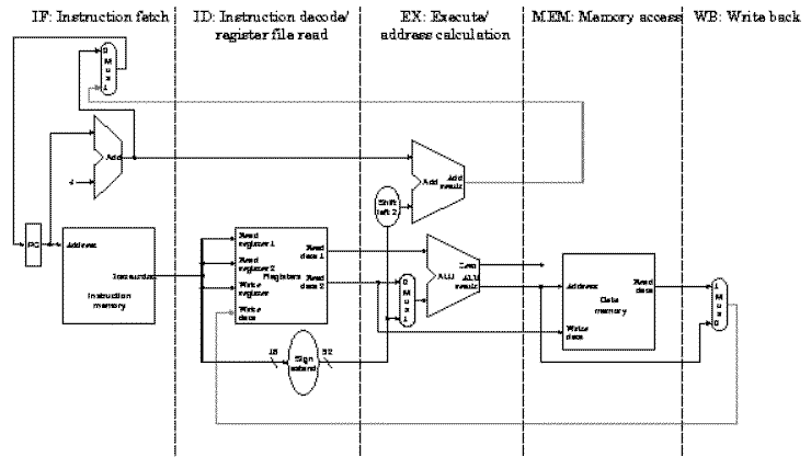
Partitioning of the MIPS single-cycle datapath developed previously, to form a pipeline processor. The segments are arranged horizontally, and data flows from left to right [Maf01,MK98].
We can represent this pipeline structure using a space-time diagram similar . Here four load instructions are executed sequentially, which are chosen because the lw instruction is the only one in our MIPS subset that consistently utilizes all five pipeline segments. Observe also that the right half of the register file is shaded to represent a read operation, while the left half is shaded to represent write.
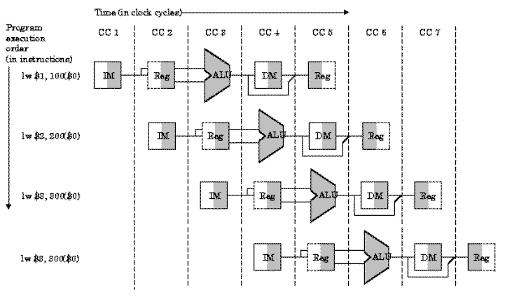
Partitioning of the MIPS single-cycle datapath developed previously, with replication in space, to form a pipeline processor that computes four lw instructions. The segments are arranged horizontally, and data flows from left to right, synchronously with the clock cycles (CC1 through CC7) [Maf01,MK98].
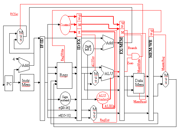
In order to ensure that the single-cycle datapath conforms to the pipeline design constraint of one cycle per segment, we need to add buffers and control between stages, similar to the way we added buffers in the multicycle datapath. These buffers and control circuitry are shown in Figure 5.4 as red rectangles, and store the results of the i-th stage so that the (i+1)-th stage can use these results in the next clock cycle.
In summary, pipelining improves efficiency by first regularizing the instruction format, for simplicity. We then divide the instructions into a fixed number of steps, and implement each step as a pipeline segment. During the pipeline design phase, we ensure that each segment takes about the same amount of time to execute as other segments in the pipeline. Also, we want to keep the pipeline full wherever possible, in order to maximize utilization and throughput, while minimizing set-up time.
In the next section, we will see that pipeline processing has some difficult problems, which are called hazards, and the pipeline is also susceptible to exceptions.
Pipeline Control and Hazards
The control of pipeline processors has similar issues to the control of multicycle datapaths. Pipelining leaves the meaning of the nine control lines unchanged, that is, those lines which controlled the multicycle datapath. In pipelining, we set control lines (to defined values) in each stage for each instruction. This is done in hardware by extending pipeline registers to include control information and circuitry.
Pipeline Control Issues and Hardware
Observe that there is nothing to control during instruction fetch and decode (IF and ID). Thus, we can begin our control activities (initialization of control signals) during ID, since control will only be exerted during EX, MEM, and WB stages of the pipeline. Recalling that the various stages of control and buffer circuitry between the pipeline stages are labelled IF/ID, ID/EX, EX/MEM, and MEM/WB, we have the propagation of control shown in Figure 5.5.
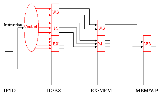
Propagation of control through the EX, MEM, and WB states of the MIPS pipelined datapath [Maf01,MK98].
Here, the following stages perform work as specified:
-
IF/ID: Initializes control by passing the rs, rd, and rt fields of the instruction, together with the opcode and funct fields, to the control circuitry.
-
ID/EX: Buffers control for the EX, MEM, and WB stages, while executing control for the EX stage. Control decides what operands will be input to the ALU, what ALU operation will be performed, and whether or not a branch is to be taken based on the ALU Zero output.
-
EX/MEM: Buffers control for the MEM and WB stages, while executing control for the MEM stage. The control lines are set for memory read or write, as well as for data selection for memory write. This stage of control also contains the branch control logic.
-
MEM/WB: Buffers and executes control for the WB stage, and selects the value to be written into the register file.
Figure shows how the control lines (red) are arranged on a per-stage basis, and how the stage-specific control signals are buffered and passed along to the next applicable stage.
